Seoul Semiconductor HE Series - what driver?
A true UV system really has to be modular, there are other things to take into consideration, a true UV light will damage surrounding plastic packaged LEDs, this means they would have to sit lower than everything else to not effect them too much. It also needs to be on a separate channel as it doesn't need to be run full time and needs to be off when you enter the room.
Find me on Instagram led_teknik
-
unkle_psycho
- LED Wizard

- Reactions:
- Posts: 1537
- Joined: Fri Apr 27, 2018 1:49 pm
Yeah, in the video marine posted they were running it 4h. Thats a good summery of concerns, it would really make sense to just build cheap small pucks.TEKNIK wrote: ↑Fri Jun 21, 2019 12:04 amA true UV system really has to be modular, there are other things to take into consideration, a true UV light will damage surrounding plastic packaged LEDs, this means they would have to sit lower than everything else to not effect them too much. It also needs to be on a separate channel as it doesn't need to be run full time and needs to be off when you enter the room.
"Nothing is true, everything is permitted"

Soooo...
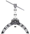
The strips arrived. And the drivers. And I cobbled together a (very amateur) parallel circuit. Each strip illuminates a separate space. I was thinking that this was going to be a plug and play dream assembly. No.
I couldn't get the push connectors on the PCBs to work. I even broke a strip of plastic off one. So I ended up soldering. Here are the results (Please don't laugh):

Note the very sloppy soldering. I hope this is not a fire risk.
I found a 1m x 20mm 9mm aluminium strip at my local hardware store. I sawed it in half, so each half is slightly shorter than the PCB They add rigidity and hopefully some heat dissipation, although neither strip is running at anywhere near optimum current (will report on this separately). These are connected by four stationery clips that also suspend each unit. Again, not ideal. I would prefer to secure using self tapping screws, but I don't have any precision drilling equipment to locate guide holes.
My biggest concern, though, is the push connectors. There is nothing in the data sheet. Perhaps I need to use a particular gauge of wire? Can anyone help with this?
Thanks,
The one t
The strips arrived. And the drivers. And I cobbled together a (very amateur) parallel circuit. Each strip illuminates a separate space. I was thinking that this was going to be a plug and play dream assembly. No.
I couldn't get the push connectors on the PCBs to work. I even broke a strip of plastic off one. So I ended up soldering. Here are the results (Please don't laugh):
Note the very sloppy soldering. I hope this is not a fire risk.
I found a 1m x 20mm 9mm aluminium strip at my local hardware store. I sawed it in half, so each half is slightly shorter than the PCB They add rigidity and hopefully some heat dissipation, although neither strip is running at anywhere near optimum current (will report on this separately). These are connected by four stationery clips that also suspend each unit. Again, not ideal. I would prefer to secure using self tapping screws, but I don't have any precision drilling equipment to locate guide holes.
My biggest concern, though, is the push connectors. There is nothing in the data sheet. Perhaps I need to use a particular gauge of wire? Can anyone help with this?
Thanks,
The one t
- Attachments
-
-
-
unkle_psycho
- LED Wizard
- Reactions:
- Posts: 1537
- Joined: Fri Apr 27, 2018 1:49 pm
Nice!
I struggled a lot with the quick connectors on bridgelux strips. At one point i would just wrestle the plastic cover off and attach wires to the metal pins under, or just solder them on. When recycling old builds I commonly just rip the wires out with brute force and solder them the next round.
I just hate how clumsy the quick connectors made me feel, when trying to operate them properly, so I kinda just turned into a mean bully and took it out on them.
Burned one led on one board while soldering, I saw that as the main risk.
Your lights are hanging pretty high. You can take a piece of paper and draw out beams at an imaginary 120 degree angle, to think about light placing. Power levels should not be toxic for your plants.
"Nothing is true, everything is permitted"