Arduino PAR and LUX Meters

Discuss garden automation systems and software here, including commercial products or Raspberry Pi and Arduino DIY setups.
User avatar
CrookedCola
LED-Curious
LED-Curious
Reactions:
Posts: 9
Joined: Fri Feb 26, 2021 2:07 pm
Location: United States

https://www.reef2reef.com/threads/diy-p ... or.800942/
... bare sensor can't measure PAR above 460-500 umol/m2/s,...
Simply add a translucent Acrylic Lens (Acrylite # 7328), at 32% Transparency its a "Glass factor" of 3.125 which increases your maximum range up to 1437.5 - 1562.5 umol/m2/s
DIY Epoxy Sealed PAR Sensors with Acrylic Lens, Peer Reviewed Documentation and Video... https://www.jove.com/t/59447/parbars-ch ... easurement
[/quote]

Thanks for sharing that link (and all the other very useful knowledge you've offered here), that is exactly what I'm looking to build. I have a few projects to complete before I'm ready for that testing rig, but I want to keep all those numbers and data in mind as I'm building my setup.

I love Linux, automation, and marijuana. DIY or DIE.
I love Linux, Automation, and Marijuana.
DIY or DIE
PeteR_1
LED Tinker
LED Tinker
Reactions:
Posts: 368
Joined: Sun Jul 05, 2020 1:10 am

CrookedCola wrote:
Fri Feb 26, 2021 7:30 pm
https://www.reef2reef.com/threads/diy-p ... or.800942/
... bare sensor can't measure PAR above 460-500 umol/m2/s,...
Simply add a translucent Acrylic Lens (Acrylite # 7328), at 32% Transparency its a "Glass factor" of 3.125 which increases your maximum range up to 1437.5 - 1562.5 umol/m2/s
DIY Epoxy Sealed PAR Sensors with Acrylic Lens, Peer Reviewed Documentation and Video... https://www.jove.com/t/59447/parbars-ch ... easurement
Thanks for sharing that link (and all the other very useful knowledge you've offered here), that is exactly what I'm looking to build. I have a few projects to complete before I'm ready for that testing rig, but I want to keep all those numbers and data in mind as I'm building my setup...
You're welcome.

One caveat about the available Translucent Acrylic sheets is that they may not be as specified by the Vendors (not the specified Manufacturer) and will require a simple field test to measure and calculate the actual % Transparency...
Lens Correction Factor is easily acquired with a properly operating TCS34725 or BH7150 sensor.
1. Setup a fixed light source (any 2700 - 5000K household bulb will work) and fixed distance between the bare sensor, measure and record the result.
2. Place the Lens over the sensor without changing the distances, measure and record the results.
3. Calculate the % Transparency by dividing result #2 by result #1 to get a decimal result (Percentage when multiplied by 100).
4. Calculate the Lens Correction Factor by dividing 1 (one) by the decimal result (or 100% / xx% Transparency).
For Example; [2000 (#2) / 4000 (#1) = 0.5 ... 1 / 0.5 = 2.0 Cf]
BTW, the Photodiodes used in the PAR Bar (Ceptometer) are available from Everlight USA for $1.00 each but were only shipped FedEx (double the cost of 10 sensors, ;)) ... https://everlightamericas.com/ambient-l ... 444a0.html
xzkeee
LED-Curious
LED-Curious
Reactions:
Posts: 1
Joined: Wed Oct 13, 2021 8:24 pm

I found a more expensive but actual par sensor,at~60$ price.
Does anyone want this?

https://item.taobao.com/item.htm?spm=a2 ... =14#detail

and I am thinking of making it into an actual par meter and sell it for around 150$.. any thought about this?
pyrocumulus
LED-Curious
LED-Curious
Reactions:
Posts: 4
Joined: Sat Oct 23, 2021 3:10 am

Hello PeteR_1,
I’ve read through this forum and am trying to condense all of this great information into something I can use for my particular situation. My interest is in quantifying the light available to my orchids and succulents. My primary goal is to get a reasonably accurate, repeatable measurement of PPFD. It would be interesting to get intensity, %RGB, etc. as well, but they are not as important to me.

It looks like the TCS34715FN sensor is no longer made and difficult to find. The TCS34725 sensor referenced here (specifically the Adafruit breakout board, PN 1334) looks like it is ready to go and already has an Arduino library available. It appears there is no need to remove the on-board LED because it can be disabled in hardware.

I don’t have a calibrated light intensity meter, nor do I have a lux to PPFD conversion factor for my particular LED lights. I bought some Barrina 2 ft grow lights but I don’t think Barrina provides conversion factors for their lights. The Amazon page for these lights has a graphic with PAR at various configurations but I don’t really trust that (https://www.amazon.com/Barrina-4-Pack-L ... B09H6K78MX).

I thought I could simply extend Adafruit’s TCS34725 breakout board Arduino library to calculate PPFD, but now I’m confused about their initial calculations (https://github.com/adafruit/Adafruit_TC ... 34725.cpp)), specifically line 417:

Code: Select all

illuminance = (-0.32466F * r) + (1.57837F * g) + (-0.73191F * b);
Where did those coefficients come from?

I read through the ams DN40 document and understand the luminance code you posted on Feb 19, 2021. I see that the PAR equation comes from the MultispeQ article, but isn’t that specific to the TCS34715FN sensor?

I also don’t know where the CPAR_cf comes from in your code.

Code: Select all

float cpar = (cdata * 0.00238663) * lens_cf;
Is 0.00238663 the lux → PPFD conversion factor for your particular lights?

Also, can you recommend a source for a ~15% translucent diffuser lens? I have seen Acrylite sheets for sale but not a lens.
Thanks!
PeteR_1
LED Tinker
LED Tinker
Reactions:
Posts: 368
Joined: Sun Jul 05, 2020 1:10 am

pyrocumulus wrote:
Sat Oct 23, 2021 3:23 am
Hello PeteR_1,
I’ve read through this forum and am trying to condense all of this great information into something I can use for my particular situation. My interest is in quantifying the light available to my orchids and succulents. My primary goal is to get a reasonably accurate, repeatable measurement of PPFD. It would be interesting to get intensity, %RGB, etc. as well, but they are not as important to me.

It looks like the TCS34715FN sensor is no longer made and difficult to find. The TCS34725 sensor referenced here (specifically the Adafruit breakout board, PN 1334) looks like it is ready to go and already has an Arduino library available. It appears there is no need to remove the on-board LED because it can be disabled in hardware.

I don’t have a calibrated light intensity meter, nor do I have a lux to PPFD conversion factor for my particular LED lights. I bought some Barrina 2 ft grow lights but I don’t think Barrina provides conversion factors for their lights. The Amazon page for these lights has a graphic with PAR at various configurations but I don’t really trust that (https://www.amazon.com/Barrina-4-Pack-L ... B09H6K78MX).

I thought I could simply extend Adafruit’s TCS34725 breakout board Arduino library to calculate PPFD, but now I’m confused about their initial calculations (https://github.com/adafruit/Adafruit_TC ... 34725.cpp)), specifically line 417:

Code: Select all

illuminance = (-0.32466F * r) + (1.57837F * g) + (-0.73191F * b);
Where did those coefficients come from?

I read through the ams DN40 document and understand the luminance code you posted on Feb 19, 2021. I see that the PAR equation comes from the MultispeQ article, but isn’t that specific to the TCS34715FN sensor?

I also don’t know where the CPAR_cf comes from in your code.

Code: Select all

float cpar = (cdata * 0.00238663) * lens_cf;
Is 0.00238663 the lux → PPFD conversion factor for your particular lights?

Also, can you recommend a source for a ~15% translucent diffuser lens? I have seen Acrylite sheets for sale but not a lens.
Thanks!
Hello,

The TCS34725 is a TCS34715 with a built-in UV/IR cut filter, the cut filter range is 'narrow' compared to PAR range, but it can and has been calibrated to PAR...
The Adafruit 'coefficients' come from the TCS34xx Document... https://ams.com/documents/20143/36005/T ... 7a1e377102
AMS TCS34725 related Documents... https://ams.com/TCS34725#tab/documents
Some of the Adafruit Library's calculations have inherent errors that directly affect PAR and %RGB, that is why I haven't used them and opted for the simpler code...

The "CPAR_Cf" (Clear Data Only PAR factor) was an exercise for... viewtopic.php?p=24937#p24937
It was used / trialed as a comparison, but is not consistent nor reliable for measuring higher intensity light sources due to 'Saturation' errors, multiple Calibration errors and has been removed from the code.

There are no "Lenses" to recommend, I just cut circles from 1/8" and 1/4" White Translucent Acrylic Sheets, stacked in multiple layers the measured Lux values are used to get the % Transmittance factors, as noted in previous posts and below.

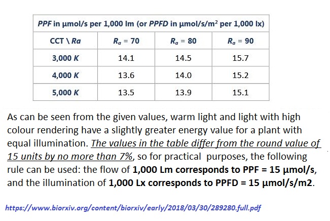
PAR is directly related to LUX for every Visible Light Source. If you are using fixed light spectrum Lux Sensor with appropriate correction factors would provide a simpler PAR only meter and they come with diffusion lens. Surprisingly six (6) BH1750FVI sensors, bare without the Lenses and from two different sources measure within 2% of a calibrated Lux Meter. Only the Lens and PAR Coefficients are required for relatively accurate measurements, no actual Lux meter calibration was needed, they appear to be "Factory Calibrated", but require the Lens Coefficient for accurate Lux measurements
BH1750FVI Lux Sensor... https://www.aliexpress.com/item/3301179 ... 4c4d1K5MYJ
Lens Correction Factor is easily acquired with a properly operating TCS34725 or BH1750 sensor.
1. Setup a fixed light source (any 2700 - 5000K household bulb will work) and fixed distance between the bare sensor, measure and record the result.
2. Place the Lens over the sensor without changing the distances, measure and record the results.
3. Calculate the % Transparency by dividing result #2 by result #1 to get a decimal result (Percentage when multiplied by 100).
4. Calculate the Lens Correction Factor by dividing 1 (one) by the decimal result (or 100% / xx% Transparency).
For Example; [2000 (#2) / 4000 (#1) = 0.5 ... 1 / 0.5 = 2.0 Cf]
As previously noted along with the installed Lens Coefficient / Correction Factor only the PAR Coefficient / Correction Factor ( float cf_par = 0.015; ) need to be changed for any specific measured White Light source... viewtopic.php?f=15&t=5756

Image

Code: Select all

//BH1750FVI with 50% light transmittance Cosine Correction Dome
// Serial Print Only. No Local Display

#include <Wire.h>

#define Addr 0x23         

void setup()
{
  Wire.begin();
  Serial.begin(9600);

  Wire.beginTransmission(Addr);
  Wire.write(0x01);
  Wire.endTransmission();

  Wire.beginTransmission(Addr);
  Wire.write(0x10);
  Wire.endTransmission();
  delay(300);
}

void loop() 
{
  unsigned int data[2];
  Wire.requestFrom(Addr, 2);

  if(Wire.available() == 2) 
  {
    data[0] = Wire.read();
    data[1] = Wire.read();
  }
    delay(300);
  
  float luminance = ((data[0] * 256) + data[1]) / 1.20;

  float cf_lux = 2.0;   // 50% transmittance Dome
  float cf_par = 0.015;  // PAR factor 4000K 90 CRI LED 

  float lux = luminance * cf_lux;
  float par = lux * cf_par;
  
  Serial.print("LUX  :");
  Serial.print(lux);
  Serial.println(" Lm/m2"); 

  Serial.print("PPFD   :");
  Serial.print(par);
  Serial.println(" umol/s-m2");   
  delay(1000);
    
BTW, you could use a bare TCS34725 Color Sensor to get the CCT and CRI to "Calibrate" / Estimate the "PAR Cf" for a BH1750 FVI PAR Sensor.
Good luck.
pyrocumulus
LED-Curious
LED-Curious
Reactions:
Posts: 4
Joined: Sat Oct 23, 2021 3:10 am

PeteR_1, thanks for all the information. I just ordered a TCS34725, a BH1750, and a couple sheets of acrylic. Hopefully I'll have something up and going to experiment with in a few days.
pyrocumulus
LED-Curious
LED-Curious
Reactions:
Posts: 4
Joined: Sat Oct 23, 2021 3:10 am

PeteR_1,
I used a BH1750 sensor with your code to derive my lens correction factors. I got a transparency value of 34.2% (correction factor = 2.92) for a 1/8" piece of Acrylite #2447 stacked on a 3/16" piece of the same material.

I then updated the lens correction factor in your TSC34725 code, leaving the lux and par factors alone. I recorded the CCT output for my lights with that sensor (3990 K).

I went back to the BH1750 code and updated cf_lux to use my lens correction factor as well as the lux --> PPF value from the table you posted using 4000 K with Ra=90 (cf_par = 0.0152). How would I estimate CRI (Ra) with the TSC34725?

The BH1750 code now outputs lux at about 7290 lm/m2 and PPFD at about 110 umol/m-s2.
For the same location, the TSC34725 outputs lux values around 5860 and PPFD values around 140.

I'm assuming I can now trust the BH1750 outputs as accurate enough for my purposes (+/- 10%). If I want to use both sensors does it make sense to adjust the lux correction factor (lux_cf) in the TSC34725 code to "calibrate" it against the BH1750?
PeteR_1
LED Tinker
LED Tinker
Reactions:
Posts: 368
Joined: Sun Jul 05, 2020 1:10 am

pyrocumulus wrote:
Tue Nov 02, 2021 9:30 pm

I used a BH1750 sensor with your code to derive my lens correction factors. I got a transparency value of 34.2% (correction factor = 2.92) for a 1/8" piece of Acrylite #2447 stacked on a 3/16" piece of the same material.
I then updated the lens correction factor in your TSC34725 code, leaving the lux and par factors alone. I recorded the CCT output for my lights with that sensor (3990 K).
I went back to the BH1750 code and updated cf_lux to use my lens correction factor as well as the lux --> PPF value from the table you posted using 4000 K with Ra=90 (cf_par = 0.0152). How would I estimate CRI (Ra) with the TSC34725?

The BH1750 code now outputs lux at about 7290 lm/m2 and PPFD at about 110 umol/m-s2.
For the same location, the TSC34725 outputs lux values around 5860 and PPFD values around 140.

I'm assuming I can now trust the BH1750 outputs as accurate enough for my purposes (+/- 10%). If I want to use both sensors does it make sense to adjust the lux correction factor (lux_cf) in the TSC34725 code to "calibrate" it against the BH1750?
The CCT measurements for TCS34725 are only Accurate for a "Bare Sensor" without a lens. The White transparent material changes the measured CCT value and requires calibration.
CRI is from the LED Manufacturer or use 80 CRI for most applications when no CRI values are known, typically 0.013 to 0.015 factors for 6000K to 3000K CCT, 80+ CRI LEDs are within +/- ~ 5%. The conversion factor increases by ~ 0.001 to 0.002 for 90+ CRI LED.

The TCS34725 requires "more calibration", where the BH1750FVI requires less. BH1750FVI (Bare Sensor and with appropriate Lens factor) measurements have been very close (+/- ~ 2%) to calibrated Lux meters.

Yes, If configured properly the BH1750FVI Lux sensors are relatively accurate usually within less than 5% to Lux Meters and could be used to calibrate a TCS34725 sensor. Yes always calibrate LUX first, then use that to calculate the PPFD... And as a last resort it could always be calibrated against an actual PAR Meter. ;)
pyrocumulus
LED-Curious
LED-Curious
Reactions:
Posts: 4
Joined: Sat Oct 23, 2021 3:10 am

Good deal. I rechecked the CCT value from the TSC34725 sensor without the lenses and it only changed a few percent. Unfortunately Barrina evidently does not publish CRI for its grow lights- a tradeoff for buying cheap lights I guess- so I'll assume CRI = 80 like you suggested. I updated the lux and PPFD correction factors for the TSC34725 based on the BH1750 outputs and now they are producing values quite close to each other. Maybe someday I'll buy a "real" PAR meter but what's the fun in that?! Now I've got two semi-calibrated PPFD sensors and I just need to wire up the temp/RH sensors to go with them. Then those values will be read into my Influx time series database for easy display via a Grafana dashboard.
Post Reply