it's just the DC side +/- going to its own 4 way wago ( 1 in to 3 out) then a + and - ran to each of the 3 right side boards.. then +/- from right set of boards to left set of boards.


if i could get this kind of talent!VandalBee wrote: ↑Wed Dec 12, 2018 3:00 amUpdate: I finally got all parts and I'm starting the build.
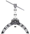
The setup will look like in the picture below. I also built a junction box that will sit on top of the driver. I used Dinkle terminal block and circuit breaker. The power is connected to the 16A 2 pole circuit breaker, which powers the driver and connects to the a set of terminal blocks that will power 9 fans - 1 for each heatsink. Then I have the driver led lines coming in the box and forming 2 separate lines. I will connect 4 lights on Line 1 and 5 on Line 2 - all boards in parallel.
hello everybody, hope you are good,LEDG wrote: ↑Fri May 10, 2019 9:28 pmLooking sharp!
I'd suggest checking the current to each board. It looks like the 3 on the right are not getting as much as the others which may mean the others are running harder than you'd like. Sometimes it's just the camera, but quite often looking at it through the camera is a good way to diagnose current disparities since it doesn't have to squint at it.
Could you post a link to the "illumi mesktek" - I googled it, but couldn't find anything.grisbi wrote: ↑Tue May 07, 2019 11:19 pmif i could get this kind of talent!VandalBee wrote: ↑Wed Dec 12, 2018 3:00 amUpdate: I finally got all parts and I'm starting the build.
The setup will look like in the picture below. I also built a junction box that will sit on top of the driver. I used Dinkle terminal block and circuit breaker. The power is connected to the 16A 2 pole circuit breaker, which powers the driver and connects to the a set of terminal blocks that will power 9 fans - 1 for each heatsink. Then I have the driver led lines coming in the box and forming 2 separate lines. I will connect 4 lights on Line 1 and 5 on Line 2 - all boards in parallel.
have to make connexion box between 8 strip ( 2 kind of strip with 3 channel each ^^ )
did you tried illumi mesktek to program by bluetooth your driver, its an amazing device, with one driver you can send current on 4 different channel .
anyway would love have so clean joinction box!
felicitation!
im gonna post really soon my work on my nichia 5000k97cri/2000k/660 strip ^^
Thx for the suggestion - current is ok, it just the angle of the camera and the picture quality that tricks the eye.LEDG wrote: ↑Fri May 10, 2019 9:28 pmLooking sharp!
I'd suggest checking the current to each board. It looks like the 3 on the right are not getting as much as the others which may mean the others are running harder than you'd like. Sometimes it's just the camera, but quite often looking at it through the camera is a good way to diagnose current disparities since it doesn't have to squint at it.
1st I water proofed the edges on the floor with silicon and then used a water barrier on the floor (its cheap solution from home depot) - a polyethylene roll 10'x12'. On top I did put some left over carpet underlayment that I had left from my last carpet installation and on top I put the Flooring Puzzle Exercise Mat. I will however have to remove it, as my room is running a bit hot, so I'm thinking to remove the floor insulation and leave it to bare concrete.