Is this relevant?
"Pt = 0.75 Vf If
Equation 1: Thermal power calculation
where:
Pt is the thermal power (W)
Vf is the forward voltage of the LED (V)
If is the source current to the LED (A)
The Vf and If can be measured directly or calculated from the PCT, so the thermal power can easily be calculated. This is the amount of
power the system/heat sink must dissipate."
"Typically, to reduce thermal resistance by 50% the heatsink volume must be quadrupled"
Here I found a calculator, that I guess can be used to estimate L-channel and U-channel, but not flat surfaces...
https://www.myheatsinks.com/calculate/t ... plate-fin/
It seemed to suggest that a 30mm U-channel had a thermal resistance of 2.5w... whatever that means
(F series -canceled) Vesta build with side lighting
-
unkle_psycho
- LED Wizard

- Reactions:
- Posts: 1537
- Joined: Fri Apr 27, 2018 1:49 pm
"Nothing is true, everything is permitted"
-
unkle_psycho
- LED Wizard
- Reactions:
- Posts: 1537
- Joined: Fri Apr 27, 2018 1:49 pm
I found a few more pieces of information, still wondering about significance.
An aluminium heatsink with fins positioned vertically has a thermal resistance of 1.8c/ w, If its positioned horizontally, like for top lighting, it has a thermal resistance of 2.2c/w
The following chart makes me feel like there is a qualitative element to heat dissipation, the law of diminishing returns does seem to be hard at work here...

Is this image suggesting a clear way to calculate aluminum volume vs watts of power?
It seems like to really calculate this at a system level, we also need other information, for example on the thermal tape/ compound used...
Tj = Pd(Θjc + Θcs + Θsa) + Ta, and
Θja = Θjc + Θcs + Θsa, or
Tj = Pd (Θja) + Ta
where:
Tj = junction temperature, °C
Pd = power dissipation, W
Θjc = junction thermal resistance, °C/W
Θcs = insulator thermal resistance, °C/W
Θsa = heat sink thermal resistance, °C/W
Θja = junction to ambient, °C/W
Ta = ambient temperature, °C
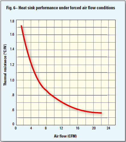
And there is also a chart on the effect of airflow on heat dissipation. I'm wondering why the scale they use here is so much more narrow then the scale they used for heatsink size?
So I found this page explaining this stuff, perhaps to students. Then they have a practice calculation which falls out of acceptable range. Here is how they describe the designers options:
"This is not a satisfactory solution: only a Tj of 98.6 °C is allowed in the example, so fine-tune the numbers in order to lower the temperature to a more reasonable level. Although this temperature is under the maximum allowable for the transistor, a look at the derating graph shows that only 2 W of dissipation is allowed at 98 °C. The transistor would have to dissipate 16 W more than it was designed to handle and would quickly fail. Lowering the ambient from 50 °C to 30 °C would yield a Tj of 78 °C and the derating curve allows over 18 W at this temperature, so this is a satisfactory heat sink, transistor, ambient temperature combination. However, if the original 50 °C is a necessary parameter, then reduce the required output power; use additional output stages; select a different power transistor (where Tj = 175 to 200 °C maximum) or heat sink or use forced-air cooling"
I understood they advise the cooling options to be to cool surrounding ambient air (not a solution without creating a compartment for the light). Then they propose reducing total power - not a real option. "use additional output stages" would seem to mean add strips (working option nro. 1). Select a transistor (read strip) that can handle the heat - no thanks. Different heatsink - well this is the entire problem. And finally use forced air cooling.
So how about a first strategy where i hook up some strips to drivers and make a first set of tests to determine how many c above ambient the Vestas run at various loads. Then I do the same with a fan, and the same using a strip of aluminium foil as a heatsink, both air cooled and without.
Whether it will work or not, at least the community will get some reference material in the process.
An aluminium heatsink with fins positioned vertically has a thermal resistance of 1.8c/ w, If its positioned horizontally, like for top lighting, it has a thermal resistance of 2.2c/w
The following chart makes me feel like there is a qualitative element to heat dissipation, the law of diminishing returns does seem to be hard at work here...
Is this image suggesting a clear way to calculate aluminum volume vs watts of power?
It seems like to really calculate this at a system level, we also need other information, for example on the thermal tape/ compound used...
Tj = Pd(Θjc + Θcs + Θsa) + Ta, and
Θja = Θjc + Θcs + Θsa, or
Tj = Pd (Θja) + Ta
where:
Tj = junction temperature, °C
Pd = power dissipation, W
Θjc = junction thermal resistance, °C/W
Θcs = insulator thermal resistance, °C/W
Θsa = heat sink thermal resistance, °C/W
Θja = junction to ambient, °C/W
Ta = ambient temperature, °C
And there is also a chart on the effect of airflow on heat dissipation. I'm wondering why the scale they use here is so much more narrow then the scale they used for heatsink size?
So I found this page explaining this stuff, perhaps to students. Then they have a practice calculation which falls out of acceptable range. Here is how they describe the designers options:
"This is not a satisfactory solution: only a Tj of 98.6 °C is allowed in the example, so fine-tune the numbers in order to lower the temperature to a more reasonable level. Although this temperature is under the maximum allowable for the transistor, a look at the derating graph shows that only 2 W of dissipation is allowed at 98 °C. The transistor would have to dissipate 16 W more than it was designed to handle and would quickly fail. Lowering the ambient from 50 °C to 30 °C would yield a Tj of 78 °C and the derating curve allows over 18 W at this temperature, so this is a satisfactory heat sink, transistor, ambient temperature combination. However, if the original 50 °C is a necessary parameter, then reduce the required output power; use additional output stages; select a different power transistor (where Tj = 175 to 200 °C maximum) or heat sink or use forced-air cooling"
I understood they advise the cooling options to be to cool surrounding ambient air (not a solution without creating a compartment for the light). Then they propose reducing total power - not a real option. "use additional output stages" would seem to mean add strips (working option nro. 1). Select a transistor (read strip) that can handle the heat - no thanks. Different heatsink - well this is the entire problem. And finally use forced air cooling.
So how about a first strategy where i hook up some strips to drivers and make a first set of tests to determine how many c above ambient the Vestas run at various loads. Then I do the same with a fan, and the same using a strip of aluminium foil as a heatsink, both air cooled and without.
Whether it will work or not, at least the community will get some reference material in the process.
Last edited by unkle_psycho on Mon May 07, 2018 2:51 pm, edited 1 time in total.
"Nothing is true, everything is permitted"
-
unkle_psycho
- LED Wizard
- Reactions:
- Posts: 1537
- Joined: Fri Apr 27, 2018 1:49 pm
One more question about the academic exercise in the post above. The way I read their problem is, that since their hot element is in a box with too high ambient temperature, it does not allow efficient heat transfer, which would get more efficient as the temperature difference increases.
Wouldn't this also mean that when we finally get our device close to room ambient temperature, it is not working very hard at all... it gets less efficient as temperatures approach each other. I guess this is why the law of diminishing returns is at play here. Takes more and more to get less and less....
Just makes me wonder why your (tazztone) strips are running so cool when obviously your heat-sinking is not 'overbuilt'.
Is there a huge difference in the temperature between the led side and the heatsink? you said your heatsink was around 41c?
"Nothing is true, everything is permitted"


ok so i found out that there was a difference between my 2 TRP 75W drivers. one would deliver full 3A to a vesta at 25.5V, while the other would automatically and instantly dim down to 1.8A 25V when i connect the same strip. i guess there is some variance in these drivers concerning how high Voltage they can go?unkle_psycho wrote: ↑Mon May 07, 2018 2:24 pmJust makes me wonder why your (tazztone) strips are running so cool when obviously your heat-sinking is not 'overbuilt'.
anyway when i measured temperature again at 2A /25.5V per strip instead of the 1.8A /25V before (both LED rows), i get 49°C. with no difference at all between the front and the back.
-
sdfoster22
- LED Maniac

- Reactions:
- Posts: 423
- Joined: Wed Apr 04, 2018 12:00 am
- Location: Ohio, USA
How long were they running when you measured temp?
NothinYet is my nickname
until the temperature stayed constant, and a minute more
-
unkle_psycho
- LED Wizard
- Reactions:
- Posts: 1537
- Joined: Fri Apr 27, 2018 1:49 pm
So Increasing the power about 10% increased the temperature by 10c...
I guess your heat transfer is working pretty well if the temperature is the same on both sides!
I just bumped into a dude selling new meanwell sp-320-24 drivers, and asking 40e each. It's about 89% efficient... it would not work with vestas right? The dude has had an add for ages, so I'm pretty sure he would sell them even cheaper then that...
"Nothing is true, everything is permitted"
i saw 87% efficiency on digikey https://www.digikey.ch/product-detail/d ... ND/7706916?
anyway i think they should work. i have no idea why my TRP doesn't supply my Vestas 3A at 25V
anyway i think they should work. i have no idea why my TRP doesn't supply my Vestas 3A at 25V
-
unkle_psycho
- LED Wizard
- Reactions:
- Posts: 1537
- Joined: Fri Apr 27, 2018 1:49 pm
The efficiency in that range should increase with voltage right? I thought the 24v one was 89%...
Well, my stuff took a day to arrive to Finland, but our local post has yet to contact me a few days later. Our postal services are worse then in the developing world. If you really need something to arrive, you need to take it yourself. I had much better experiences with China mail.
I guess I should aim at max efficient drivers, now that I have a flexible bunch to test and play around with... Drivers are the least aging tech in leds, so I'll likely have to tolerate these choices for a while...
"Nothing is true, everything is permitted"
-
unkle_psycho
- LED Wizard
- Reactions:
- Posts: 1537
- Joined: Fri Apr 27, 2018 1:49 pm
So I googled CFM of a typical table fan and it seems to be around 1000CFM. Looking at the aircooling chart above I'm really wondering if air-cooling isn't the best way to cool the top strips...
"Nothing is true, everything is permitted"